Skip to content

TROY'S 3D PRINTED RC CRJ-900/CRJ-700 AIRLINER

Advertising
?
Creation quality: 5.0/5 (2 votes)
Evaluation of members on the printability, utility, level of detail, etc.

  • 28.5k views
  • 103 likes
  • 72 downloads
  • 1 collection
  • 8 comments

Licence CULTS - Private Use
Last update 2023-09-03 at 02:01
Publication date 2023-08-07 at 21:59
Design number 1370608
3D design format
ZIP Folder details Close
  • CRJ-900 STL Files.zip
    • -Parts/ TPU Hinge X25.stl
    • -Parts/Battery Tray.stl
    • -Parts/Contol Horns X3.stl
    • -Parts/Engine Brace.stl
    • -Parts/Flap Horns X2.stl
    • -Parts/Main Gear.stl
    • -Parts/Nose Gear Stearing Clevis.stl
    • -Parts/Nose Gear.stl
    • -Parts/Reverse Servo Mount.stl
    • -Parts/RX Mount.stl
    • -Parts/Servo Mount Left.stl
    • -Parts/Servo Mount Right.stl
    • -Parts/Universal Servo Mount.stl
    • -Parts/x2 80%FSA Thrust Tube.stl
    • -Parts/x2 90%FSA Thrust Tube.stl
    • -Parts/x2 Inner Nacelle.stl
    • -Parts/x2 Motor Mount.stl
    • -Parts/x2 Nose Gear Rim.stl
    • -Parts/x2 Nose Gear Tire.stl
    • -Parts/x2 Outer Nacelle.stl
    • -Parts/x3 Wing Attachment.stl
    • -Parts/x4 Main Gear Rim.stl
    • -Parts/x4 Main Gear Tire.stl
    • Fuselage/F1 Front Window.stl
    • Fuselage/F1 Window Frame.stl
    • Fuselage/F1.stl
    • Fuselage/F10.stl
    • Fuselage/F11.stl
    • Fuselage/F2.stl
    • Fuselage/F3.stl
    • Fuselage/F4 Battery Hatch.stl
    • Fuselage/F4.stl
    • Fuselage/F5.stl
    • Fuselage/F6.stl
    • Fuselage/F7.stl
    • Fuselage/F8.stl
    • Fuselage/F9.stl
    • Tail/Elevator 1 Connected.stl
    • Tail/Left Elevator 1.stl
    • Tail/Left Elevator 2.stl
    • Tail/Left Horizontal Stabilizer 1.stl
    • Tail/Left Horizontal Stabilizer 2.stl
    • Tail/Right Elevator 1.stl
    • Tail/Right Elevator 2.stl
    • Tail/Right Horizontal Stabilizer 1.stl
    • Tail/Right Horizontal Stabilizer 2.stl
    • Tail/Rudder.stl
    • Tail/Vertical Stabilizer.stl
    • Tail/Vertical Stabilzer Top.stl
    • Wing/Ailerons Connected.stl
    • Wing/Center 1.stl
    • Wing/Center 2.stl
    • Wing/Inner Flaps Connected .stl
    • Wing/Left Aileron.stl
    • Wing/Left Flap Gap.stl
    • Wing/Left Inner Flap.stl
    • Wing/Left Outer Flap.stl
    • Wing/Left Wing 1 W: CG embedded.stl
    • Wing/Left Wing 1.stl
    • Wing/Left Wing 2.stl
    • Wing/Left Wing 3.stl
    • Wing/Left Wing 4.stl
    • Wing/Left Wing Tip.stl
    • Wing/Outer Flaps Connected .stl
    • Wing/Right Aileron.stl
    • Wing/Right Flap Gap.stl
    • Wing/Right Inner Flap.stl
    • Wing/Right Outer Flap.stl
    • Wing/Right Wing 1.stl
    • Wing/Right Wing 2.stl
    • Wing/Right Wing 3.stl
    • Wing/Right Wing 4.stl
    • Wing/Right Wing Tip.stl
    • -Parts/ CRJ Stencil/Fuselage 900 Stencil.stl
    • -Parts/ CRJ Stencil/Fuselage CRJ Stencil.stl
    • -Parts/ CRJ Stencil/Tail CRJ Stencil.stl
  • New 70mm EDF Nacelle.zip
    • 70mm EDF Inner Nacelle x2.stl
    • 70mm EDF Outer Nacelle x2.stl
    • 70mm EDF Motor Mount x2.stl
    • 70mm EDF 85% FSA Tube x2.stl

Learn more about the formats

3D printer file info

3D model description

This is a fully 3D printed CRJ-900 I designed to be easy to assemble and fun to fly.

You can also build this as a CRJ-700 if you would like. All you need to do is leave out fuselage part 3. I have not built on and test flown it myself so make sure to send me some picture if you build on for yourself.

Build Volume required for this airplane is 200x200x200.

RTF weight: 3,300g (PLA 2x 4s 2200mah)
Wingspan: 1.5m
Length: 2m
Print time: 120hrs
2kg of PLA

I have a full step by step assemble guide on my YouTube channel.
https://youtu.be/D8aDJ5Wal5c

Here is an rcgroups build thread: https://www.rcgroups.com/forums/showthread.php?4396017-Troy-McMillan-CRJ-700-900

This plane has flaps and retractable landing gear. I designed this to use a 6ch receiver. A key feature that allows this to happen are the special design of the servo brackets that allow you to mount the servos in any orientation. This makes it possible to use a y harness to connect all the control surfaces. If you have the ability to use more channels I would recommend that for the flaps and ailerons so an 8ch setup would be ideal but if you only have access to 6ch it will work great.

I do not use any carbon fiber rods in this build to make it easy to source the parts required. There is a spar intentionally designed into the wing sections, that make it very strong. I did add a location to add a 8mm x 500mm carbon fiber tube if you would like to add a traditional spar.

I designed a NEW 70mm EDF engine Nacelle for this CRJ-900. The 64mm required full power to get off the runway for the maiden flight with not much extra power. Basically almost flew to scale, for RC models it is good to have a bit of excess power if needed. This will allow for a bit shorter takeoff role and be more efficient to fly. You can still use 64mm if you would like to. The 64mm will be ok for LW or regular PLA it will just be a bit more difficult to fly. I would say if you are using regular PLA I would recommend the 70mm EDFs and if you are using LW-PLA you can use the 64mm EDFs.

Here is the link to the 70mm EDFs I used with 80amp ESC. https://amzn.to/3YZ2UIw

*If you would like to print the wing using LW-PLA it will save around 1000grams, but it is not required. I have not flown it in LW-PLA, but I designed it with LW-PLA in mind. Printing it fully out of PLA shows how well it flies with that additional weight. I printed an entire one out of LW-PLA and made sure I could set the CG. I have not flown it yet but I will be sure to and add a video for you.

** LANDING GEAR **
For the landing gear as you can see from my maiden flight the 3d printed struts did not hold up. I did make them a standard length to hopefully make easy to find aluminum gear. The nose strut is 50mm from the top of the strut to the center of the axle with 30mm diameter tires. The main strut is 60mm from the top of the strut to the center of the axle with 50mm diameter tires. The shank from the retracts is 4mm.

I have a complete list of parts required for this build on my YouTube assembly guide.

Here is a link to the Decals:
Coming soon!

3D printing settings

All The Fuselage Parts are designed with a 15mm ring this is a key feature for strength so before you print the parts make sure this ring shows up on your slicer software.

Fuselage 1-10 Print will 15mm ring on the build plate. Set the Extruder closer than standard to the bed. This is also referred to as Z-Offset, I set mine up so the extruder is almost touching the bed. The first layer will print on the bed without the 15mm ring, the second layer will start a 15mm ring. You want the second layer to adhere to the bed, the first layer does not matter. Turn off skirts or brims.
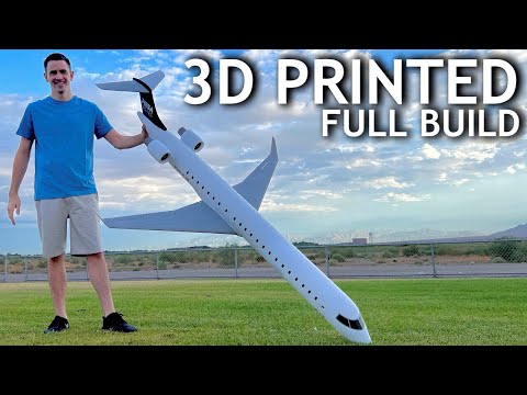
FUSELAGE

Fuselage 1-11:
Layer Height - 0.2
*Initial Layer Height - 0.15
Wall Line Count - 1
Top Layer - 0
Bottom Layer - 4
Initial Bottom Layer - 0
Extra Skin Wall Count - 5
Skin Removal Width - 3.5 mm
Infill Density - 0%
Surface Mode - Normal
Build Plate Adhesion Type - None

Battery Hatch:
Layer Height - 0.2
*Initial Layer Height - 0.15
Wall Line Count - 1
Top Layer - 5
Bottom Layer - 5
Initial Bottom Layer - 5
Extra Skin Wall Count - 0
Skin Removal Width - 5mm
Infill - 0
Surface Mode - Normal

Front Window Frame & Windows:
Layer Height - 0.2
*Initial Layer Height - 0.15
Wall Line Count - 10
Top Layer - 5
Bottom Layer - 5
Initial Bottom Layer - 5
Extra Skin Wall Count - 5
Skin Removal Width - 3.5
Infill - 0
Surface Mode - Normal

WING

Center Wing 1 & 2 , Left & Right Wing 1:
Layer Height - 0.2
*Initial Layer Height - 0.15
Wall Line Count - 1
Top Layer - 0
Bottom Layer - 0
Initial Bottom Layer - 0
Infill - 0
Surface Mode - Normal

Left & Right Wing 2-4:
Layer Height - 0.2
*Initial Layer Height - 0.15
Wall Line Count - 1
Top Layer - 0
Bottom Layer - 4
Initial Bottom Layer - 0
Infill - 0
Surface Mode - Normal

Wing Tip:
Layer Height - 0.2
*Initial Layer Height - 0.15
Wall Line Count - 1
Top Layer - 0
Bottom Layer - 4
Initial Bottom Layer - 4
Infill - 0
Surface Mode - Normal

Flap Gap:
Layer Height - 0.2
*Initial Layer Height - 0.15
Wall Line Count - 1
Top Layer - 4
Bottom Layer - 4
Initial Bottom Layer - 4
Extra Skin Wall Count - 0
Skin Removal Width - .42mm
Infill - 0
Surface Mode - Normal

Left & Right Ailerons, Inner & Outer Flaps:
Layer Height - 0.2
*Initial Layer Height - 0.15
Wall Line Count - 1
Top Layer - 0
Bottom Layer - 4
Initial Bottom Layer - 4
Extra Skin Wall Count - 0
Skin Removal Width - 1.5mm
Infill - 0
Surface Mode - Normal

TAIL

Vertical Stabilizer:
Layer Height - 0.2
*Initial Layer Height - 0.15
Wall Line Count - 1
Top Layer - 0
Bottom Layer - 0
Initial Bottom Layer - 0
Infill - 0
Surface Mode - Normal

Vertical Stabilizer Top:
Layer Height - 0.2
*Initial Layer Height - 0.15
Wall Line Count - 1
Top Layer - 10
Bottom Layer - 4
Initial Bottom Layer - 0
Extra Skin Wall Count - 0
Skin Removal Width - 3mm
Infill - 0
Surface Mode - Normal

Rudder:
Layer Height - 0.2
*Initial Layer Height - 0.15
Wall Line Count - 1
Top Layer - 4
Bottom Layer - 4
Initial Bottom Layer - 4
Extra Skin Wall Count - 0
Skin Removal Width - 1.5mm
Infill - 0
Surface Mode - Normal

Right & Left Horizontal Stabilizer 1, Right & Left Elevator 1 :
Layer Height - 0.2
*Initial Layer Height - 0.15
Wall Line Count - 1
Top Layer - 0
Bottom Layer - 4
Initial Bottom Layer - 4
Extra Skin Wall Count - 0
Skin Removal Width - 5mm
Infill - 0
Surface Mode - Normal

Right & Left Horizontal Stabilizer 2, Right & Left Elevator 2:
Layer Height - 0.2
*Initial Layer Height - 0.15
Wall Line Count - 1
Top Layer - 0
Bottom Layer - 4
Initial Bottom Layer - 0
Extra Skin Wall Count - 5
Skin Removal Width - 3mm
Infill - 0
Surface Mode - Normal

PARTS

Inner & Outer Nacelle:
Layer Height - 0.2
*Initial Layer Height - 0.15
Wall Line Count - 1
Top Layer - 7
Bottom Layer - 0
Initial Bottom Layer - 0
Extra Skin Wall Count - 5
Skin Removal Width - 3mm
Infill - 0
Build Plate Adhesion Type - Brim
Surface Mode - Normal

Motor Mount:
Layer Height - 0.2
*Initial Layer Height - 0.15
Wall Line Count - 1
Top Layer - 0
Bottom Layer - 4
Initial Bottom Layer - 0
Extra Skin Wall Count - 5
Skin Removal Width - .42mm
Infill - 0
Surface Mode - Normal

Thrust Tube: I used 80% for my Build
Layer Height - 0.2
*Initial Layer Height - 0.15
Wall Line Count - 1
Top Layer - 0
Bottom Layer - 0
Initial Bottom Layer - 0
Infill - 0
Spiralize Outer Contour: Checked
Surface Mode - Normal

Battery Tray, Control Horns, Engine Brace, Servo Mounts, RX Mount & all Gear Parts :
Layer Height - 0.2
*Initial Layer Height - 0.15
Wall Line Count - 5
Top Layer - 6
Bottom Layer - 4
Initial Bottom Layer - 4
Infill - 20% Grid
Surface Mode - Normal

Tires printed with TPU:
Layer Height - 0.2
*Initial Layer Height - 0.15
Wall Line Count - 2
Top Layer - 4
-Nose Wheel zero bottom layers
Bottom Layer - 4
Initial Bottom Layer - 4
Infill - 15% Grid
Print Temperature - 210
Flow - 115%
Infill & Wall Speed - 20mm/s
Surface Mode - Normal

Tires printed with Varioshore TPU:
Layer Height - 0.2
*Initial Layer Height - 0.15
Wall Line Count - 3
Top Layer - 4
-Nose Wheel zero bottom layers
Bottom Layer - 4
Initial Bottom Layer - 4
Infill - 20% Grid
Print Temperature - 240
Flow - 60%
Infill & Wall Speed - 30mm/s
Surface Mode - Normal

Advertising


Issue with this design? Report a problem.

Advertising

Would you like to support Cults?

You like Cults and you want to help us continue the adventure independently? Please note that we are a small team of 3 people, therefore it is very simple to support us to maintain the activity and create future developments. Here are 4 solutions accessible to all:

  • ADVERTISING: Disable your banner blocker (AdBlock, …) and click on our banner ads.

  • AFFILIATION: Make your purchases online by clicking on our affiliate links here Amazon.

  • DONATE: If you want, you can make a donation via Ko-Fi 💜.

  • WORD OF MOUTH: Invite your friends to come, discover the platform and the magnificent 3D files shared by the community!

Advertising
100% secure payment with PayPal or Credit Card.