The whole system was test printed on a Bambu Lab X1, but also a large Ender 5 plus. It has been sliced with Bambu Lab Studio (Prusa slicer clone), and also with Cura 5, both with excellent results. You need a build volume of at least 200x200mm.
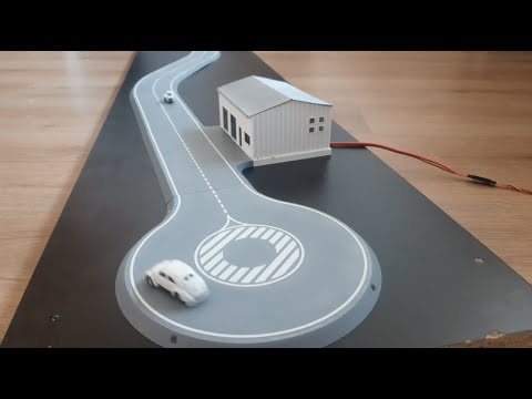
First, have a look at the introduction movie. ( and September update.)
For each of the steps in the build process, you can find additional info and slicer settings here:
Step 1: printing the track
The tracks are printed with matte grey PLA, I got the best results with the Matte grey from Bambu Lab. The matte PLA from eSun I tried also had a nice finish, but was a bit harder to print.
Optional: printing the double lane road with markings found here:
If you have a multi material printer, you can print the white lines and grey body in 1 go. But this can also be done with a "normal single extruder" printer by printing the white lines first (it is just 1 layer), and then switching the filament to grey and printing the grey body on top of it. (The tracks you see in the video are printed this way). I provided STL files for both ways of printing.
Beware that the build plate surface will determine the look of your road surface. Smooth is cool, but using a textured PEI plate also renders a very nice result!
You should use the standard print settings in your slicer for PLA, using a 0.4 nozzle and 0.2mm layer height.
Step 2: laying the track
The track in the video is the smallest track possible, but depending on the power of your servo, the number of corners you are using, and the amount of cars you want running, you can go up to 6 meters in length. (Probably more, but I ran out of room ;)
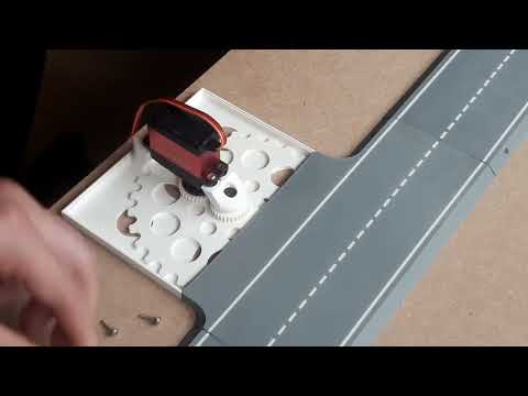
Step 3: drive unit
The drive unit pieces were printed with regular PLA. You could print the sprocket and servo gear with a "stronger" material, but after a 5 hour endurance test and more than 20 hours of total running, there is no "tear and wear" noticeable whatsoever, so I don't see the need.
You should use the standard print settings in your slicer for PLA, using a 0.4 nozzle and 0.2mm layer height.
The servo gear should fit on the round servo horn that comes with your servo. If it doesn't fit, you could just glue them together with some CA glue, but be sure the gear is placed exactly in the middle and does not wobble. Therefore, you should sand the servo horn flat before attaching the gear.
The servo you will need is a standard size continuous (360°) servo. Although you can power a small track like this with a regular 5kg servo, for a few bucks more you can buy a 30kg servo, which will offer a lot more power if you want to "grow" your track later on. If you plan to use the U-turn, you will need a more powerful servo, because this turn creates extra friction.
You need a drive unit for each lane you want to power. So, for instance, in the oval demo track, you can also power the inner lane by placing another drive unit in the inside of the oval.
Step 4: the chain
The chain should be printed with regular PLA as fine as possible. In Bambu Studio I used the "0.08 mm Extra fine" preset. On the large Ender 5 plus printer, I used Cura's "super quality" profile and dialed back the line/wall width from 0.4 to 0.3mm on a 0.4 nozzle to get the best result.
Also enable the "elephant foot compensation" and set seam position to "random" in both slicers.
If this doesn’t work for you, you can try to print “chain 20 pcs V2.stl”. This is a version which has more clearance between the chain links, and can be printed on standard “fine” settings (or even on standard settings if not available). Both versions are compatible with each other.
The magnets you need to get for the chain have to be between 1-2mm thick and max 5x5mm in width. When gluing multiple magnets to the chain, be sure to check the polarity , so that they all are oriented the same way.
If you run into problems later when the magnet doesn't slide smoothly between two road pieces (e.g., when your board isn't perfectly flat), you should place the magnet between two "spacer links", which will help the link glide from one piece to another.
Step 5: car setup
There is no right or wrong when choosing the size of magnet for your car, the easiest option is to use the same ones as your chain. The rule is simple: the further away the magnet is from the road surface, the stronger it needs to be. It is a matter of finding the right distance, so that there is as little friction as possible, and the car still runs smoothly without "jittering".
In order to test this out, I included a "needle car", with a couple of different wheel sizes. Changing the wheel size will shorten or elongate the distance between the magnet and the road surface. This way you can quickly test it out before gluing the magnet onto the actual car you want to use.
You could also use a very small magnet (2mm) and glue it on a "lip" made from some scratch PLA. (Like the guide lips from the Faller car system). This will ensure smooth movement, but after some use, it will leave a "slide mark" on your road surface, so I prefer the former option.
If your car has wheels that have a bit of grip on the surface (most cars have rubber tires), you only have to use 1 magnet. But if the wheels slide a lot (like the PLA wheels of the needle car), you need to glue 2 magnets on your car (13mm or 26mm apart). This will make them take corners better. Remember to glue 2 magnets on the chain also.
Be sure to check the polarity before gluing the magnet to your car!
Step 6: powering up
If you use a light servo on a small track, you can get away with using a servo tester if it can handle the amps.
But most likely, you will need a "heavier" solution that can draw more current.
If you have an RX setup lying around, you can use this. It has the added advantage of not having to deal with wires going from your control center to the drive unit. I have tested an old cheap RX setup with a 2-channel receiver and a lipo battery, and it works just fine.
The most elegant and future proof solution is to hook up an Arduino. You will need a simple Arduino (like the UNO), a 10kΩ potentiometer and a 5V power supply. This is a simple setup that anyone can handle. Wiring diagram and the Arduino code sketch are included.
Bill of purchase
- PLA (about 15g per road piece), examples:
- Screws
- self tapping M1.5-2 (#2 for every road piece, length depending on your board thickness)
- self tapping M3-M3.5 (#2, length depending on your board thickness)
- optional: M1.5-1.8 x 6 (#2, or use CA glue)
- Continuous (360°) servo(#1 for each lane you want to power) examples_:_
- Magnets between 1-2mm thick and max 5x5mm in width (min #2 per car), examples:
- Optional: Arduino power setup
- Arduino UNO
- 10kΩ Potentiometer
- 5V power supply